기능성모듈(MCU, Utility)
|
조립키트,부품(DIY Assembly)
|
전자기기 및 제어 (Control)
|
주문,제작,개발 (Order Base)
→ 저항1/4W
→ 저항1/8W
→ 저항1W
→ 저항2W
→ 가변저항
→ 쎄라믹콘덴서
→ 마일러콘덴서
→ LED
→ FND & LCD
→ 쎈서
→ 코일
→ 릴레이
→ 스피커
→ 마이크
→ MICOM
→ TTL IC
→ DOIDE
→ C MOS IC
→ OP AMP
→ TR & FET
→ SCR & Thyristor
→ 써미스타,바리스타
→ 모터&솔레노이드
상품명 + 규격
상품명
규격
상품설명
조립키트,부품(DIY Assembly)
>
센서,신호검출
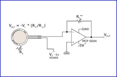
압력센서 [A401]
압력이 가해지면 저항값이 변화하는 쎈서입니다.
반응범위 : ~ 110Nr
출력저항값 : 무한대 ~ 1.5 Kohm
크기 : 9mm 두께 : 0.45mm
*가격 :
판매불가
Thickness 0.208 mm (0.008 in.)
Length 56.8 mm (2.24 in.)
Width 31.8 mm (1.25 in.)
Sensing Area 25.4 mm (1 in.) diameter
Connector 2-pin Male Square Pin
Substrate Polyester (ex: Mylar)
Pin Spacing 2.54 mm (0.1 in.)
Force Range:
0 - 25 lb. (110 N)
Hardware
The Flexiforce Pressure Sensor is essentially a variable resistor. When no pressure is applied, the resistance between the two outer leads is incredibly large, probably greater than 10 Mega Ohms (more than my meter can measure). When pressure is applied, the resistance measured between the outer leads lowers until you've reached the max pressure it's intended to measure. In this case that's about 25 lbs of pressure, and the current Flexiforce Pressure sensor I'm using measures about 50K Ohms when given that max amount of pressure.
You can test the range of your sensor using a multimeter. Just attach the two outer leads to the multimeter and set the meter to measure resistance. Then squeeze the sensor and watch the resistance value change.
Now, let's read values with an Arduino. To do this, we create a voltage divider circuit with the Flexiforce sensor and an extra resistor. I picked 1M Ohm in this example because it's about in the middle of the Flexiforce sensor's dynamic range. Many other similar values could work as well.
Connect 5V to one side of the voltage divider, and GND to the other. In the middle, where the Flexiforce sensor and the resistor connect, connect one of the analog-in pins of the Arduino with a jumper wire. In this case I used pin A0. Here is a Fritzing diagram of the setup:
유틸전자주식회사
| 서울시 용산구 청파로74 전자랜드본관 광장층 C-31호 | E-mail:
aprogara@naver.com
| 사업자번호: 106-86-72446
Tel:050-5500-4900 Hosting Server www.nexgeo.co.kr|개인정보책임자:김영현 | 통신판매업 용산00261호
◈자신 있습니다. 회로개발
키폰헤드셋, 전화헤드셋, 상담용전화기, 미니전화기, RF리모콘, 무선리모콘, 플랜트로닉스, PLANTRONICS, 벨코, 켄트, 도아, 경진, 다산, 아이알링크, 폴리콤, 삼정통신,
◈주문제작 및 개발해 드립니다. 통신 및 전자기기
절체기, 지령대, 보류음, MOH, 자동응답기, 자동다이얼러, 발신번호표시, 무인교환, 선로시험기, 허브,공유기, 전화회의, 사운드스테이션, SOUNDSTATION, 전화녹음,
◈재고 충분 합니다. 완성 모듈 및 키트제품
통화녹음, 녹취기, 전화방송, ARS, 통신케이블, 전원선, 잡자재, 동축케이블, 단자함, 몰딩, 아웃렛, 시험탄기, 피뢰탄기, 원텐블럭, 음성메모리, 마이컴, 통화중검출, 인포렉스, 스타렉스,
◈납품합니다. 전자 부품
모타제어, 무선모듈, PICBASIC, 스위칭파워, PABX, 교환기, 키폰, 자동제어, 원격제어, 비상호출, 유틸전자, 아프로가, APROGA, 통신개발, 주문제작, 통신기기, 전자기기, 텔레마케팅, 전자랜드, 용산
◈설계 및 구축 해드립니다. 자동제어 및 전자파