기능성모듈(MCU, Utility)
|
조립키트,부품(DIY Assembly)
|
전자기기 및 제어 (Control)
|
주문,제작,개발 (Order Base)
→ MCU,Avr,Arduino
→ 콘트롤, 기능성모듈
→ 타이머,카운터,온도
→ 쎈서모듈
→ 디스플레이
→ 드라이버
→ 통신,WiFi,블루투쓰
→ 앰프,POWER,기타
상품명 + 규격
상품명
규격
상품설명
기능성모듈(MCU, Utility)
>
쎈서모듈
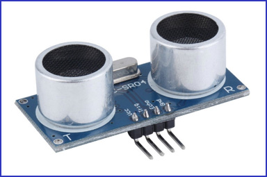
초음파거리검출센서 [HC-SR04]
-> 초음파 거리쎈서모듈입니다.
1. Induction angle: not more than 15 degrees
2. 거리 : 2 Cm - 2.4 Meter
3. 배선: VCC, trig (control side), echo (receiving end), GND
4. DC 5V
*가격 :
4,400 원
Power - 5v, 30mA Typ.
Frequency - 40KHz.
Size - 43mm x 20mm x 17mm height.
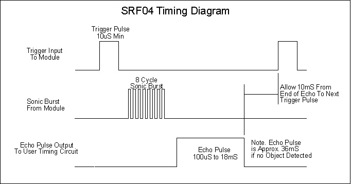
The input Trigger is a 10uS Min. TTL level pulse
Echo Pulse is Positive TTL level signal, with the width proportional to the object range.
This project started after I looked at the Polaroid Ultrasonic Ranging module. It has a number of disadvantages for use in small robots etc.
The maximum range of 10.7 metre is far more than is normally required, and as a result
The current consumption, at 2.5 Amps during the sonic burst is truly horrendous.
The 150mA quiescent current is also far too high.
The minimum range of 26cm is useless. 1-2cm is more like it.
The module is quite large to fit into small systems, and
It’s EXPENSIVE.
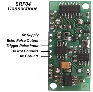
The SRF04 was designed to be just as easy to use as the Polaroid sonar, requiring a short trigger pulse and providing an echo pulse. Your controller only has to time the length of this pulse to find the range. The connections to the SRF04 are shown below:
The SRF04 Timing diagram is shown below. You only need to supply a short 10uS pulse to the trigger input to start the ranging. The SRF04 will send out an 8 cycle burst of ultrasound at 40khz and raise its echo line high. It then listens for an echo, and as soon as it detects one it lowers the echo line again. The echo line is therefore a pulse whose width is proportional to the distance to the object. By timing the pulse it is possible to calculate the range in inches/centimeters or anything else. If nothing is detected then the SRF04 will lower its echo line anyway after about 36mS.
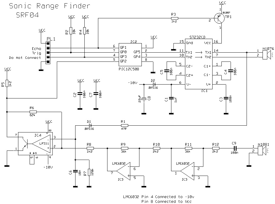
The circuit is designed to be low cost. It uses a PIC12C508 to perform the control functions and standard 40khz piezo transducers. The drive to the transmitting transducer could be simplest driven directly from the PIC. The 5v drive can give a useful range for large objects, but can be problematic detecting smaller objects. The transducer can handle 20v of drive, so I decided to get up close to this level. A MAX232 IC, usually used for RS232 communication makes and ideal driver, providing about 16v of drive.
The receiver is a classic two stage op-amp circuit. The input capacitor C8 blocks some residual DC which always seems to be present. Each gain stage is set to 24 for a total gain of 576-ish. This is close the 25 maximum gain available using the LM1458. The gain bandwidth product for the LM1458 is 1Mhz. The maximum gain at 40khz is 1000000/40000 = 25. The output of the amplifier is fed into an LM311 comparator. A small amount of positive feedback provides some hysterisis to give a clean stable output.
The problem of getting operation down to 1-2cm is that the receiver will pick up direct coupling from the transmitter, which is right next to it. To make matters worse the piezo transducer is a mechanical object that keeps resonating some time after the drive has been removed. Up to 1mS depending on when you decide it has stopped. It is much harder to tell the difference between this direct coupled ringing and a returning echo, which is why many designs, including the Polaroid module, simply blank out this period. Looking at the returning echo on an oscilloscope shows that it is much larger in magnitude at close quarters than the cross-coupled signal. I therefore adjust the detection threshold during this time so that only the echo is detectable. The 100n capacitor C10 is charged to about –6v during the burst. This discharges quite quickly through the 10k resistor R6 to restore sensitivity for more distant echo’s.
A convenient negative voltage for the op-amp and comparator is generated by the MAX232. Unfortunately, this also generates quite a bit of high frequency noise. I therefore shut it down whilst listening for the echo. The 10uF capacitor C9 holds the negative rail just long enough to do this.
In operation, the processor waits for an active low trigger pulse to come in. It then generates just eight cycles of 40khz. The echo line is then raised to signal the host processor to start timing. The raising of the echo line also shuts of the MAX232. After a while – no more than 10-12mS normally, the returning echo will be detected and the PIC will lower the echo line. The width of this pulse represents the flight time of the sonic burst. If no echo is detected then it will automatically time out after about 30mS (Its two times the WDT period of the PIC). Because the MAX232 is shut down during echo detection, you must wait at least 10mS between measurement cycles for the +/- 10v to recharge.
Performance of this design is, I think, quite good. It will reliably measure down to 3cm and will continue detecting down to 1cm or less but after 2-3cm the pulse width doesn’t get any smaller.
Maximum range is a little over 3m. As and example of the sensitivity of this design, it will detect a 1inch thick plastic broom handle at 2.4m.
Average current consumption is reasonable at less than 50mA and typically about 30mA.
Download the source code and a ready assembled hex file.
Calculating the Distance
The SRF04 provides an echo pulse proportional to distance. If the width of the pulse is measured in uS, then dividing by 58 will give you the distance in cm, or dividing by 148 will give the distance in inches. uS/58=cm or uS/148=inches.
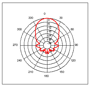
Changing beam pattern and beam width
You can't! This is a question which crops up regularly, however there is no easy way to reduce or change the beam width that I'm aware of. The beam pattern of the SRF04 is conical with the width of the beam being a function of the surface area of the transducers and is fixed. The beam pattern of the transducers used on the SRF04, taken from the manufacturers data sheet, is shown below.
*회로설계,주문제작,개발용 부품 및 모듈 전문점
유틸전자주식회사
서울 용산구 한강로 3가 16-9 전자랜드 본관 광장층 C31호
02-706-7700 aproga@korea.com www.UTIL.co.kr
유틸전자주식회사
| 서울시 용산구 청파로74 전자랜드본관 광장층 C-31호 | E-mail:
aprogara@naver.com
| 사업자번호: 106-86-72446
Tel:050-5500-4900 Hosting Server www.nexgeo.co.kr|개인정보책임자:김영현 | 통신판매업 용산00261호
◈자신 있습니다. 회로개발
키폰헤드셋, 전화헤드셋, 상담용전화기, 미니전화기, RF리모콘, 무선리모콘, 플랜트로닉스, PLANTRONICS, 벨코, 켄트, 도아, 경진, 다산, 아이알링크, 폴리콤, 삼정통신,
◈주문제작 및 개발해 드립니다. 통신 및 전자기기
절체기, 지령대, 보류음, MOH, 자동응답기, 자동다이얼러, 발신번호표시, 무인교환, 선로시험기, 허브,공유기, 전화회의, 사운드스테이션, SOUNDSTATION, 전화녹음,
◈재고 충분 합니다. 완성 모듈 및 키트제품
통화녹음, 녹취기, 전화방송, ARS, 통신케이블, 전원선, 잡자재, 동축케이블, 단자함, 몰딩, 아웃렛, 시험탄기, 피뢰탄기, 원텐블럭, 음성메모리, 마이컴, 통화중검출, 인포렉스, 스타렉스,
◈납품합니다. 전자 부품
모타제어, 무선모듈, PICBASIC, 스위칭파워, PABX, 교환기, 키폰, 자동제어, 원격제어, 비상호출, 유틸전자, 아프로가, APROGA, 통신개발, 주문제작, 통신기기, 전자기기, 텔레마케팅, 전자랜드, 용산
◈설계 및 구축 해드립니다. 자동제어 및 전자파